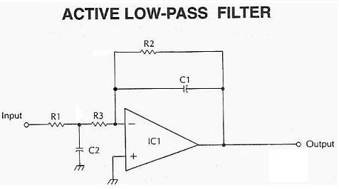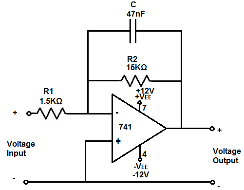
fc = 1 / 2πRCĪs described in previous tutorial fc is cut-off frequency and the R is Resistor value and the C is Capacitor value. The Cut off frequency formula is same as used in passive low pass filter. Here the violate line shows us the traditional passive low pass RC filter we seen in previous tutorial. This is the image of Active low pass filter. Here is the simple Low pass filter design:. This Active low pass filter is work in the same way as Passive low pass filter, only difference is here one extra component is added, it is an amplifier as op-amp. Low pass filter filtered out low frequency and block higher one of an AC sinusoidal signal. In the first tutorial of Passive low pass filter, we had learned what was Low Pass filter. Amplify is a magnifying glass, it produces a replica of what we see but in bigger form to recognize it better. Let’s Explore further and understand what is special about it.Īctive Low Pass Filter with Amplification:īefore understanding Active low pass filter design with op-amp, we need to know a little bit about Amplifiers. The output gain and bandwidth as well as frequency response are dependable on the op-amp specification.

Thus the name Active low pass filter.Ī typical Amplifier draws the power from the external power supply and amplifies the signal but it is highly flexible as we can change the frequency bandwidth more flexibly. As this requires voltage source, it’s an active component. This Amplification is done by operational amplifier or op-amp.

We learned in the previous tutorials that passive low pass filter work’s without any outer interruption or active response. Only two passive components resistor and capacitor is the key or heart of a passive low pass filter circuit. What is it, Circuit, formulas, curve?Īs we know from previous tutorial, Passive low pass filter works with passive components. Previously we described passive low pass filter, in this tutorial we will explore what is an Active Low Pass Filter.


 0 kommentar(er)
